WHAT IS A RESISTANCE
(ELECTRONICS - What is RESISTOR)
(ELECTRONICS - What is RESISTOR)
Electronics, Electricity, Electrical, Fundamentals, Theory of Resistivity, Resistance or Resistor, Resistance of a Wire, How to Measure a Resistance, Resistance and Super Conductivity, Ohm's Law; Resistance and Ohm's Las, RESISTANCE IN PARELELL, RESISTANCE IN SERIES, Resistance and Load, Resistance and Wattage, Resistance of a Battery, Resistance of a Bulb, Resistance of a Circuit, How to Calculate the Resistance - in a Circuit, Resistance and Multimeter, Multimeter and Resistance, Ohm Meter, Ammeter, Voltmeter, Galvanometer and Resistance - Resistivity; Resistance of a Galvanometer; THEORY OF RESISTIVITY; OHM'S LAW THEORY; FORMULA OF RESISTANCE - OHMS LAW; HOW TO CALCULATE RESISTANCE OF A RESISTOR - OHM'S LAW; Resistance of a Coil, Resistance of a Motor, Resistance of a Super Conductor; Resistance of a Computer; Resistance of TFT, Resistance of a Printer, Resistance of CPU FAN, Resistance of a CONDENSOR; Resistance of a Parellel Plate Condensor; Resistance of an ELECTRICAL WIRE; Resistance of a Filament; Kirchhoff’s Law and Resistance, Resiatance - Kirchoff's Law; LAW OF RESISTANCE; LAW OF RESISTIVITY; RESISTANCE OF GOLD, RESISTANCE OF SILVER; RESISTANCE OF SEMICONDUCTORS; RESISTANCE OF COPPER; RESISTANCE OF METALS; RESISTANCE OF WATER; RESISTANCE OF NON-METALS; Resistance of Plastic; Resistance of Glass Rod; Resistance of Gases; Resistance of Salts; Resistance of Human Body (Electrical); Voltage and Resistance of Human Body; Resistance of Spinal Cord; Resistance of Human Brain; Electronic Signals in Human Brain and Resistivity; Electrons and Resistance; Photons and Electronic Resistance; Resistance of Photo Cell; Resistance of CADMIUM SULPHIDE;
What is a Resistor (or Resistance Materials) :
A linear resistor is a linear, passive two-terminal electrical component that implements electrical resistance as a circuit element. The current through a resistor is in direct proportion to the voltage across the resistor's terminals. Thus, the ratio of the voltage applied across a resistor's terminals to the intensity of current through the resistor is called resistance. This relation is represented by Ohm's law:
The electrical functionality of a resistor is specified by its resistance: common commercial resistors are manufactured over a range of more than nine orders of magnitude. When specifying that resistance in an electronic design, the required precision of the resistance may require attention to the manufacturing tolerance of the chosen resistor, according to its specific application. The temperature coefficient of the resistance may also be of concern in some precision applications. Practical resistors are also specified as having a maximum power rating which must exceed the anticipated power dissipation of that resistor in a particular circuit: this is mainly of concern in power electronics applications. Resistors with higher power ratings are physically larger and may require heat sinks. In a high-voltage circuit, attention must sometimes be paid to the rated maximum working voltage of the resistor.
Practical resistors have a series inductance and a small parallel capacitance; these specifications can be important in high-frequency applications. In a low-noise amplifier or pre-amp, the noise characteristics of a resistor may be an issue. The unwanted inductance, excess noise, and temperature coefficient are mainly dependent on the technology used in manufacturing the resistor. They are not normally specified individually for a particular family of resistors manufactured using a particular technology.[1] A family of discrete resistors is also characterized according to its form factor, that is, the size of the device and the position of its leads (or terminals) which is relevant in the practical
What is a Resistor (or Resistance Materials) :
A linear resistor is a linear, passive two-terminal electrical component that implements electrical resistance as a circuit element. The current through a resistor is in direct proportion to the voltage across the resistor's terminals. Thus, the ratio of the voltage applied across a resistor's terminals to the intensity of current through the resistor is called resistance. This relation is represented by Ohm's law:

The electrical functionality of a resistor is specified by its resistance: common commercial resistors are manufactured over a range of more than nine orders of magnitude. When specifying that resistance in an electronic design, the required precision of the resistance may require attention to the manufacturing tolerance of the chosen resistor, according to its specific application. The temperature coefficient of the resistance may also be of concern in some precision applications. Practical resistors are also specified as having a maximum power rating which must exceed the anticipated power dissipation of that resistor in a particular circuit: this is mainly of concern in power electronics applications. Resistors with higher power ratings are physically larger and may require heat sinks. In a high-voltage circuit, attention must sometimes be paid to the rated maximum working voltage of the resistor.
Practical resistors have a series inductance and a small parallel capacitance; these specifications can be important in high-frequency applications. In a low-noise amplifier or pre-amp, the noise characteristics of a resistor may be an issue. The unwanted inductance, excess noise, and temperature coefficient are mainly dependent on the technology used in manufacturing the resistor. They are not normally specified individually for a particular family of resistors manufactured using a particular technology.[1] A family of discrete resistors is also characterized according to its form factor, that is, the size of the device and the position of its leads (or terminals) which is relevant in the practical
Ohm's Law :
Main article: Ohm's law
The behavior of an ideal resistor is dictated by the relationship specified by Ohm's law:
Equivalently, Ohm's law can be stated:

Series and Parallel Resistors :
Main article: Series and parallel circuits
In a series configuration, the current through all of the resistors is the same, but the voltage across each resistor will be in proportion to its resistance. The potential difference (voltage) seen across the network is the sum of those voltages, thus the total resistance can be found as the sum of those resistances:

Resistors in a parallel configuration are each subject to the same potential difference (voltage), however the currents through them add. The conductances of the resistors then add to determine the conductance of the network. Thus the equivalent resistance (Req) of the network can be computed:


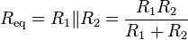
A resistor network that is a combination of parallel and series connections can be broken up into smaller parts that are either one or the other. For instance,


One practical application of these relationships is that a non-standard value of resistance can generally be synthesized by connecting a number of standard values in series and/or parallel. This can also be used to obtain a resistance with a higher power rating than that of the individual resistors used. In the special case of N identical resistors all connected in series or all connected in parallel, the power rating of the individual resistors is thereby multiplied by N.
Power Dissipation :
The power P dissipated by a resistor (or the equivalent resistance of a resistor network) is calculated as: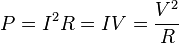
The first form is a restatement of Joule's first law. Using Ohm's law, the two other forms can be derived.
The total amount of heat energy released over a period of time can be determined from the integral of the power over that period of time:

Resistors required to dissipate substantial amounts of power, particularly used in power supplies, power conversion circuits, and power amplifiers, are generally referred to as power resistors; this designation is loosely applied to resistors with power ratings of 1 watt or greater. Power resistors are physically larger and tend not to use the preferred values, color codes, and external packages described below.
If the average power dissipated by a resistor is more than its power rating, damage to the resistor may occur, permanently altering its resistance; this is distinct from the reversible change in resistance due to its temperature coefficient when it warms. Excessive power dissipation may raise the temperature of the resistor to a point where it can burn the circuit board or adjacent components, or even cause a fire. There are flameproof resistors that fail (open circuit) before they overheat dangerously.
Note that the nominal power rating of a resistor is not the same as the power that it can safely dissipate in practical use. Air circulation and proximity to a circuit board, ambient temperature, and other factors can reduce acceptable dissipation significantly. Rated power dissipation may be given for an ambient temperature of 25 °C in free air. Inside an equipment case at 60 °C, rated dissipation will be significantly less; a resistor dissipating a bit less than the maximum figure given by the manufacturer may still be outside the safe operating area and may prematurely fail.
Electrical Resistance and Conductance
The electrical resistance of an electrical element measures its opposition to the passage of an electric current; the inverse quantity is electrical conductance, measuring how easily electricity flows along a certain path. Electrical resistance shares some conceptual parallels with the mechanical notion of friction. The SI unit of electrical resistance is the ohm (Ω), while electrical conductance is measured in siemens (S).
An object of uniform cross section has a resistance proportional to its resistivity and length and inversely proportional to its cross-sectional area. All materials show some resistance, except for superconductors, which have a resistance of zero.
The resistance of an object is defined as the ratio of voltage across it to current through it:

In the case of a nonlinear conductor (not obeying Ohm's law), this ratio can change as current or voltage changes; the inverse slope of a chord to an I–V curve is sometimes referred to as a "chordal resistance" or "static resistance".
Conductors and Resistors :
Objects such as wires that are designed to have low resistance so that they transfer current with the least loss of electrical energy are called conductors. Objects that are designed to have a specific resistance so that they can dissipate electrical energy or otherwise modify how a circuit behaves are called resistors. Conductors are made of highly conductive materials such as metals, in particular copper and aluminium. Resistors, on the other hand, are made of a wide variety of materials depending on factors such as the desired resistance, amount of energy that it needs to dissipate, precision, and cost.
Causes of Resistance :
In metals
A metal consists of a lattice of atoms, each with a shell of electrons. This is also known as a positive ionic lattice. The outer electrons are free to dissociate from their parent atoms and travel through the lattice, creating a 'sea' of electrons, making the metal a conductor. When an electrical potential difference (a voltage) is applied across the metal, the electrons drift from one end of the conductor to the other under the influence of the electric field.
Near room temperatures, the thermal motion of ions is the primary source of scattering of electrons (due to destructive interference of free electron waves on non-correlating potentials of ions), and is thus the prime cause of metal resistance. Imperfections of lattice also contribute into resistance, although their contribution in pure metals is negligible.
The larger the cross-sectional area of the conductor, the more electrons are available to carry the current, so the lower the resistance. The longer the conductor, the more scattering events occur in each electron's path through the material, so the higher the resistance. Different materials also affect the resistance.
In Semiconductors and Insulators
In metals, the Fermi level lies in the conduction band (see Band Theory, below) giving rise to free conduction electrons. However, in semiconductors the position of the Fermi level is within the band gap, approximately half-way between the conduction band minimum and valence band maximum for intrinsic (undoped) semiconductors. This means that at 0 kelvins, there are no free conduction electrons and the resistance is infinite. However, the resistance will continue to decrease as the charge carrier density in the conduction band increases. In extrinsic (doped) semiconductors, Dopant Atoms increase the majority charge carrier concentration by donating electrons to the conduction band or accepting holes in the valence band. For both types of donor or acceptor atoms, increasing the dopant density leads to a reduction in the resistance. Highly doped semiconductors hence behave metallic. At very high temperatures, the contribution of thermally generated carriers will dominate over the contribution from dopant atoms and the resistance will decrease exponentially with temperature.In Ionic Liquids/Electrolytes
In electrolytes, electrical conduction happens not by band electrons or holes, but by full atomic species (ions) traveling, each carrying an electrical charge. The resistivity of ionic liquids varies tremendously by the concentration - while distilled water is almost an insulator, salt water is a very efficient electrical conductor. In biological membranes, currents are carried by ionic salts. Small holes in the membranes, called ion channels, are selective to specific ions and determine the membrane resistance.Resistivity of Various Materials
Main article: electrical resistivities of the elements (data page)
| Material | Resistivity, ρ ohm-metre |
| Metals | 10−8 |
| Semiconductors | variable |
| Electrolytes | variable |
| Insulators | 1016 |
| Superconductors | 0 (exactly) |
Ohm's Law :

The mathematical equation that describes this relationship is:
The law was named after the German physicist Georg Ohm, who, in a treatise published in 1827, described measurements of applied voltage and current through simple electrical circuits containing various lengths of wire. He presented a slightly more complex equation than the one above (see History section below) to explain his experimental results. The above equation is the modern form of Ohm's law.
In physics, the term Ohm's law is also used to refer to various generalizations of the law originally formulated by Ohm. The simplest example of this is:

I read your article, very informative and userinformatic info are mentioned. For second hand iphone in Dubai also a best deal for iphone. Keepit up bro to share more article like that. Thanks for sharing this ones
ReplyDelete